The contents
The construction of the house, the overhaul of an apartment or renovating a garage is inextricably linked to the connection of electricity meter. Most consumers believe that to organize a similar process under force only to the professional, and will be wrong. A careful study of the instructions supplied with the purchased device, familiarization with the schemes and the recommendations of the expert will allow the connection of the meter to clean.

Classification of instruments for metering of electricity ↑
A couple of decades ago all the apartments and houses were equipped with identical meters. Now the picture has changed dramatically, so when the meter selection should pay attention to the following parameters:
- There are AC and DC type of current used.
- In the apartments, according to the scheme, it is possible to connect single-phase meter exclusively for private homes with the option of installing three phase metering device.
- Number of tariffs distinguish between single – and multi-types.
- Depending on the type of operating mechanism, there are mechanical and electronic meters. Extremely rare hybrid options when the inductive measuring unit is combined with a digital interface.
- By connection type, there are primary and secondary inclusions. In a domestic environment are used scheme, only the direct connection. The last option is for areas where there are high current loads (at substations, at the entrance to multi-storey building, i.e. when connected to the grid through transformers).

The mechanism of action of electricity presented is inductive or electronic device. The first option applies to older models and rapidly displaced from the market. Its main drawback is the possibility of unfair exploitation. Avoid losses when paying for the services allows the connection of electronic meters, which actively promote a government program. Compactness, accuracy and ability to operate in multirate mode – the main advantages of the electronic models.
The most common variant is a single-phase meter direct connection, the scheme of its installation, we consider in detail.
The legislative basis of self-connection ↑
To prevent problem situations before an independent electric meter installation should contact the local branch services and sales. The agreement and permits will confirm the consistency of your actions. Issued an employee documents will include requirements for strict compliance before work and immediately when I connect the meter according to the scheme.
The law stipulates that the installation of electricity meters in the private sector should be done outside of premises. This condition allows free access of the inspector and sales to the readings account equipment. Apartment owners carry out the connection according to the scheme in a designated place which is usually located on the landing.

Basic installation requirements ↑
Connect the meter according to the scheme is conducted strictly in accordance with the rules developed TB during the operation of electrical equipment. What you should know:
- Work is being done on the condition that the air temperature exceeds +5onC. Exposure to cold negatively affects the work elements contained in the wiring diagram.
- Installation of electricity meter in open space involves the construction of a sealed Cabinet, preferably with heating. Required tools and parts were easy to find in specialized stores.
- Connect the meter, according to the scheme, is made at a height of one meter to 1.7 m. This is done for ease of reading.
Additional terms and conditions are available for the visit to the power company for the contract.
Preparatory work ↑
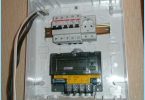
Connect the meter, according to the scheme, preceded by preparatory actions, in particular, the procedure of mounting box for installation of all electrical equipment. A significant proportion of advanced metering presents a modular instances, so their installation is done with a special mounting rail. It helps to alleviate the whole process of connection. In the same way, attach other appliances relating to protective equipment.

Special boxes (panels) are mounted and recessed, different in size. Their choice depends on the installation location and number of fixed devices contained in the connection diagram. The mounting box includes the following steps:
- To remove the top cover unscrewed the screws.
- Fastening depends on the surface where is fixed the Boxing for the concrete you will need dowels, wooden surface is easier to use screws.
After secure attachment of the box are transferred to the installation of modular equipment.

Installation of electric meter and related devices ↑
According to the EMP in the wiring before the meter is ouzo. Usually for this purpose, use the automatic double pole switch. Its main functions according to the connection diagram, are the following:
- To prevent the meter short circuit.
- Protection device against fire as a result of exceeding the permissible load level.
- To provide preventative treatment or replacement of the meter.
- Limit the allowed capacity.
If sealing the controlling organization of the RCD in the box is impossible, it is set in a designated area on the landing. The process of sealing is an attachment on both sides on the screws contacts special stickers. For the meter contains a lead or plastic seals. Locking double-pole induction machine is carried out on a DIN rail due to the special latch located at the rear of the device. Then, the connection scheme provides for the fixation of the meter, which is similar to previous actions. In conclusion, there is mounting SPST machines. This installation is a modular equipment in accordance with the scheme completed at the final stage are transferred to the connection of the meter and related devices.

Connection ↑
Before connecting according to the scheme of the meter needs to be training. The Central portion of the bottom cover equipped with a sealing screw which must be unscrewed, after which the protective coating is removed. The reverse side of the cover must contain a connection diagram of the meter purchased.
Contacts ↑
All four pins of the metering device is equipped with two clamping screws. This ensures a uniform connection wires to the contact plate. The need for quality pressure due to the further sealing of the meter and lack of free access to contacts. The purpose of the device contacts of the account is as follows:
- the first connection of the supply phases;
- the second connects the exhaust phase;
- the third connection of the supply neutral conductor;
- fourth, accordingly, records the outgoing neutral wire.
The pin functions input protection device:
- the top row provides the connection of the wires feeding the premises (house, apartment or garage);
- the wires coming to the meter, connected on the bottom row.
Purpose contact SPST machines located after the meter, the following:
- phase C of the meter goes to the top row;
- the lower contacts connect the wires containing waste phase and a group of power consumption.

The connection of the RCD and electric meter ↑
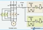
Starts the connection of the proposed scheme with the introduction of the device automation. For this core wire feed start on the top row of contacts on the left and the phase wire on the right is zero.
After installation, introduction to machine the leads pass to connect the meter in accordance with the scheme. The procedure begins with the lower row of contacts of the protective device. The action is similar to the process in the top row: the left connects the phase to the right – zero. After partial removal of the jumper insulation, cores are brought into contact and clamped with a screwdriver. Connection diagram can be as follows:
- the lower contact of the induction machine on the left (phase) is the first contact of the meter;
- the lower right contact of the protective device (zero), the third contact of an electricity meter;
- the second contact device of the contact on top of a single pole of the machine, located behind the electric meter;
For the distribution coming from the electric meter phase between multiple machines it is recommended to use copper bus factory production. This will greatly simplify the whole process. Avoid touch the wires between them always left a gap.


For the remaining contact of the counter is prepared connecting cable with zero bus, whose main task is the distribution of the zero waste areas. After its installation in the Boxing pass to the elimination phase of the lower contacts SPST machines appliances power consumption and making them the wiring from a zero tyres. This process of embodiment of the wiring connection in life has been completed and the meter is ready for operation. The final touch is to put on the lid and secure it with a filling screw.