The contents
Today, fluorescent lamps are one of the most common sources of artificial lighting. This is because the lamps of this type is several times more economical than the usual us standard devices incandescent bulb and cheaper than led.

Fluorescent species today are found almost at every step: in offices, hospitals, schools and homes.
How does ↑
The fluorescent lamp is a gas discharge device, within which is formed the discharge among the pairs of spirals. The data spiral is nothing like the anode and cathode, they are located on both sides. Visible light appears when the ultraviolet radiation from mercury vapor. This contributes to the deposited on the inner surface of the lamp luminophor – a substance that includes phosphorus and other elements.
Fluorescent lamps operate through a special device –the ballast apparatus, which is another name for the choke. Many models imported function as a standard choke, and with a device for automatic work. The last distributed as electronic ballast machines.
The advantages of the devices operating on electronic ballasts
Among the positive qualities of these models are the following:
- absence of flicker;
- no noise;
- relatively light weight;
- the best ignition;
- saving electricity.
Each fluorescent lamp has a number of advantages over standard filament lamp:
- durability;
- efficiency;
- a big light output.
However, this technology has a significant drawback – if the room temperature is not more than five degrees, the ignition of such a lamp occurs slowly, and the light from it dimmer.
Wiring diagram ↑
There are several wiring diagrams for fluorescent lamps.
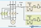
If you use electronic ballasts, the wiring diagram looks like the following:

- With the compensation capacitor;
- LL– throttle;
- EL– fluorescent lamp;
- SF– starter.
As a rule, in practice, the most common lamps that use two transducers connected in series. In this scheme they connect is:


A – for fluorescent models 20 (18) W
For luminous models with a capacity of 40 (36) W
When used two lamps, it is possible to reduce pulsation of the total luminous flux. This is due to the fact that the pulsation of the individual lamps are not synchronous, that is, a small shift in time. In this regard, will never be equal to zero, the value of the total luminous flux. Another name of the scheme, when applied from two lamps is a circuit split phase. An important advantage is that it does not require additional measures to improve the power factor. Another advantage is that at lower voltage, total luminous flux remains stable.
When connecting, be sure to consider that the capacity of the choke and lamp must be identical. If the capacity of the second large, then you may want to use two throttle.
However, despite all the obvious advantages, it is necessary to specify one drawback of such models. They all contain this unsafe substance as mercury is in liquid form. To date, there is disposal problem of such devices that have failed, so the use of fluorescent lamps is a threat to the environment.
If when mounting the lamp accidentally slipped from his hand and shatters, you can see the small balls of mercury that are rolled along the ground.
The following describes a detailed wiring diagram complete with electromagnetic ballast.
- Power on the circuit. Then it passes through the choke and filaments, and then to the starter motor terminals;
- starter – there is nothing like a neon bulb with two contacts. One of these contacts is welded bimetal plate;
- the tension begins to ionize the neon. Through the starter current begins to flow much power, warming the gas and the plate of the bimetal;
- the plate begins to bend and close the starter motor terminals;
- electric current passes through closed circuit, whereby the filament is heated;
- this warm-up and gives impetus for the emergence of the lamps glow in the conditions of lower stress;
- at the time when the lamp begins to glow, the starter starts to drop voltage. It falls to such a level when the ion is no longer able to ionize. The starter automatically shuts down and the filaments cease to be under the influence of current.
To ensure the functioning of the lamps, set the choke. This device is used to limit the current to the required value, depending on capacity. Thanks to the self-inductance makes it possible to reliably start lamps.
The pros and cons of lamps with electromagnetic ballast ↑
Design and scheme of these lamps is quite simple. However, despite this, they are distinguished by high reliability and relatively low cost, but they have drawbacks.
Among them:
- there is no guarantee of start at low temperature;
- flickering;
- the probability of a low-frequency hum;
- increased consumption of electricity;
- quite a lot of weight and dimensions.
Fluorescent lamps of the compact type ↑
Many modern fluorescent lamps of the type suitable for lighting of industrial premises. However, for home use they are inconvenient due to the large size and inappropriate design. Technology does not stand still and today created such devices, which have small-sized electronic ballast. Patent compact fluorescent lamp was poluchen 80-ies of the last century, however they became used in everyday life not so long ago. Today, the size of the compact fluorescent models do not exceed the usual standard. With regard to the principle of operation remain the same. At the ends of the bulb there are two filament. That’s between them and you receive the arc discharge, which produces ultraviolet waves. Under the influence of these waves is the phosphor.
How much is the compact valve ↑
Compact lamp manufacturer, should be about ten thousand hours. However, due to the constant instability of the mains voltage,the lifetime of devices is greatly reduced. To reduce lifetime impact and frequency on and off in the circuit, as well as operating in conditions of high or conversely too low temperatures. According to statistics, the most common reason these devices fail is a blown filament channel.