People who have electric stoves, have served for decades, often are interested in wiring diagrams burners. This is not surprising because over time these items fail, and the only way to fix it is to install new burners.
In theory, under ideal operating conditions, the burner can serve almost forever, but, of course, does not happen. The fact that we often forget to shut it off, causing the heating elements heating up to unimaginable temperatures. In some cases, on the surface of a blown burner, you can even see the cracks. But this only applies to old models with new this is not happening.

When blows the burner plate, the owner must think about adding a new element. Needless to say, that no scheme is not enough. Of course, it should be in the technical passport of the product. But you have to admit that after 20 years, the documents are lost or come in unreadable condition.
Wiring diagrams of popular plates ↑
Dream 8 ↑

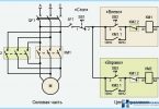
This is one of the most popular plates of the past. Not surprisingly, the kitchens, many people can see it. It consists of the following key components:
- Ten E1+ E2,
- Ten E3-E5,
- S1-S4,
- F,
- indicators.
The heating elements E1-2 are located respectively in rings 1 and 2. It can easily be seen in the diagram in the technical documentation of the plate. Ten of E3-E5 is an oven. S1-S4 represent switching hub, which allows you to manage the stove.
Indicators available in the cooker, in accordance with the scheme there are two types of HL1 and HL. They are responsible for work Elements. Also available HL3. But it’s just the backlight glowing wardrobe that has always been the opportunity to see in what state the dish.
For adjustment of the degree of heating corresponds to the switch S1. It has four positions, which provide different intensity of the fire. In the first closed position P1-2 and P2-3.
When this happens, it activates the heater E3. The current will be the following route:
- it all starts with contact HR,
- then comes relay F,
- P1-2,
- E4-5 + E3,
- P2-3.
The first destination is a contact plug. This heating element is connected in series to the fourth Coil and the fifth. Moreover, it is connected in parallel with the second and third. In all of this you can easily make your own by looking at the diagram below.

When it switches to position number two, it activates P1-1 and P2-3. Of course, the circuit through which the current passes, is changing. It all starts with the contact plugs located at the bottom, which is signed as XP. Then follow these points:
- F,
- R1-1,
- E3,
- P2-3.
Ends with plug XP, which is at the top. When enabled, this circuit runs exclusively ten E3. Increasing the capacity is possible to achieve by reducing resistance. The main advantage of this scheme connecting the burners of electric stoves is that it is possible, at a constant voltage, which is 220V.
For S1 there is a position number 3. In this case the circuit P1-1 and P2-2. Because of this, there is a connection of the heating elements E4+5. If you talk about S4, this switch is responsible for the operation of the lamp. The standard scheme of the burner to the appliance it is designated as HL3.
ELEKTRA 1002 ↑

Second, the most commonly used in homes and apartments with electric stove is ELEKTRA 1002. So to know about the wiring diagram of the burner — is a must. Fortunately, it is not particularly difficult and it can handle even a beginner.
So, in the presence of electric stoves have four burners, of course, the connection scheme has its own. The first two heating elements have indexes Н1и H2. The main difference is the tubular structure.
The third ring are in the wiring diagram the appliance has an index N3. It is made of cast iron and is quite large — 200 mm. N4 is also made of cast iron. Its size is 145 mm.
For temperature control responsible regulators P1 and P2. They have no as such levels of power. But this disadvantage is compensated with a seven-speed switches P3 and P4. In turn, PH is responsible for the oven and has 3 positions.
The lock responds to the switch P5. Warning light of burner in the scheme of the appliance is L1-4. Fifth L allows you to illuminate the oven. Also available L6. It turns on when the closet is reached the suitable temperature.
For heating the oven meet elements respectively H5-6. Seven is the grill. The thermostat is indicated by a simple letter T. Also in the presence of a keyboard switch is B. the Seventh L light the oven.
Schemes for other popular models ↑

Unconditional, electric ELEKTRA 1002 and a Dream 8 was one of the most popular at the time. But now people prefer to buy themselves the products of other brands, among the most famous we can remember Gorenje and Hansa. Their plate most of the sets in their kitchens.
You can also recall the brand «Lysva». Of course, their plate now, few purchases, if you have the opportunity to purchase the products of a more reputable brand, however the circle of customers the company is quite large. In General, below you will find wiring diagrams of burners of electric stoves from top brands.

Using this wiring diagram burner cookers you will easily perform all the work yourself. But for quality implementation will not prevent at least a basic knowledge of operation of power networks and electrical appliances.
The nuances of connecting the heating element and its verification ↑

Heater ensures normal operation of the burner appliance. In fact, it is its main element, which is essential for the normal functioning of the whole scheme. But that all has gone well, you should take into account many nuances. Among the highlights are:
- The contact connection should not touch the body of the appliance, otherwise the connection may end in tears.
- Contacts should be isolated. Best for this purpose, suitable sleeve. In a pinch you can use ordinary electrical tape. But its reliability is not in the example worse.
- It is very important to test the ten burners of the appliance to the connection scheme was successful.
To test the ten burners of the electric stove you will need a special device. It is called an ohmmeter. The multimeter is also good enough for this purpose. These devices are designed to measure the resistance in the circuit.
If you are using a multimeter, the first step is to configure the appropriate measuring mode. Then two wires must be connected to relevant sockets.

Then you need to turn on the device. With two probes you can measure the resistance of the heating elements. To do this required the probes to be connected to the contacts of the heating burners for electric stoves.
If your measuring instrument is a digital multimeter after connecting the probes to the contacts — display will immediately show the result. There are three possible positions:
- the gap,
- completely unusable,
- resistance.
Of course, to connect the heating element of the burner to the stove according to the scheme it is necessary that the multimeter showed the third position. Otherwise it will not work.
After connection of the heating appliance each person the question arises, and will then work the ring? Whether all the wires are connected correctly? This is especially true when it comes to burners.
For diagnostics you will need the same device. Before testing the load off the appliance, turn on the power switch and connect the test probes to the plug. The display will show the appropriate result.
The results ↑
To connect the burner and all its elements to the electric scheme is easy. Enough to have a matching schema and a basic knowledge of functioning of electric networks and electric.